Entries tagged as making
Friday, July 14. 2023
Construction report QRP-Labs.com QMX

In 2019, I decided to build the QCX monoband-TRX to have a lightweight TRX that serves a radio band that should be okay to use throughout the year, 40 m. I was still building up a basic ham radio gear “portfolio” and didn’t own HF antennas that could specifically be used for SOTA. I could be using an end-fed for SOTA, I thought, but didn’t own a compact telescopic mast to be able to lift the wire up on a summit. I do own the MFJ-1979 telescopic vertical, though, that I sometimes use when operating HF from the car. But, it is only resonant on 20 m and up. For 40 m, I’d have to add the extra coil. The MFJ-1979 alone is already quite heavy, though, even more together with the coil. So, I got the idea of buying the QCX-mini for 20 m, which would reduce some weight for both TRX and ANT, and 20 m would raise chances for DX during the summer season when I intended to roam summits. I’d still need to carry a small tripod, though, for the vertical.
Then came the QMX, the same size as the QCX-mini, but a multi-bander for 80/60/40/30/20 m! This would be the solution, and I purchased one kit at the QRP-Labs booth at the HAM RADIO fair in Friedrichshafen last month, right after walking through the doors.
Assembly promised to be not so adventurous as that of the QCX anymore, as all resistors, several capacitors and all ICs were already SMD-soldered to the PCB. I still had to wind the filters and transformers, though, and add the other components. A funny thing to read in the assembly manual was, that Hans somehow got aware that left-handers wind mirrored toroids. I mentioned this in my QCX construction report, the toroids end up a bit skewed on the PCB. Since the QMX PCB is much more compact, this would be an important thing to keep in mind. To achieve the same result, I also wound the toroids counter-clockwise, left-handed, but starting at the 12 o’clock position, not at 6 o’clock, like the right-handers do.
This was already my assembly report! ![]() I’ll only mention some stumbling blocks I experienced.
I’ll only mention some stumbling blocks I experienced.
First, it is obvious that the assembly manual is in an early stage. While there aren’t any real errors in it, it can be a bit confusing due to sections of the QDX assembly manual having been pasted in, obviously. So, I got the first shock when turning on the TRX for the first time, it staid dully dark. But, reading a bit closer into different sections, I read that the QMX initially starts in firmware update mode, that is, it was simply just a USB thumb drive at that point, nothing more! The picture in the manual showed a happily glowing display with a frequency reading, though. I connected the QMX to the notebook, pushed the power button once more, and voilà, a new drive appeared! I could successfully copy the firmware file to it.
When I measured power output into a dummy load, I could read about 4 watts when feeding the QMX about 13 volts from a LiFePO4 battery. I didn’t do any alignment, because there isn’t a description of this procedure yet. A thing that disturbed me was that extremely loud noise in the headphones on key release. I inspected the PCB closely, but didn’t find anything suspicious. So, I went to the QRP-Labs group. There, I learnt that the QMX offers a USB terminal console with a configuration menu! That’s not too surprising, after all, as the QMX is an SDR-based TRX. In the config menu, I went to Band Configuration and set the “TX/RX param 2” value from “0” to “1”, and a reboot had this issue resolved!
Later, there was a topic discussed in the group about the QMX being quite deaf at 20 m. Hans proposed some solutions, and I went with his recommended solution #2. That means: It is enough to wind the 20 m (19 windings) and 30 m (11 windings) sections onto L401. Have the windings spread out such that the 20 m tap goes one place further into the 30 m hole, and the 30 m tap to the 40 m hole. Then patch the 40 m to the 80 m hole, and do the configuration changes for the BPF. (This is already adapted in version 1.00f of the manual.) The BPF frequency sweep diagram looks promising; this is another awesome feature of the terminal console.
When using the optional enclosure, it is important that the control PCB can pass through the outlet in the display PCB easily. Therefore, you should take care that all protruding elements are honed away, just as mentioned in the manual. You can carefully wiggle on the controls to help it pass through. And that reminds me of another stumbling block: One following day, the TRX suddenly didn’t turn on anymore. I removed the enclosure, put apart the PCBs and connected them again, then the TRX turned on again. I suspect that the left control’s outer hull was touching the DC socket’s back. Therefore, be sure to put some insulating tape over the control’s left side and/or the DC socket’s back. Also, when soldering the controls themselves, don’t use too much solder. Initially, I made another short-circuit that disabled volume control.
Apropos volume control, that one was difficult to tame. Sidetone volume always was too loud, I had to turn the volume down before keying and up afterwards. Also, turning the left control didn’t really turn the RX volume down counter-clockwise or up clockwise. Rather, the volume was cycling between a few different levels when the knob was turned into one direction. I seemed to have tamed this behavior by either insulating the control from the DC socket (as described above) or by setting sidetone volume to 005 in the menu.
An interesting feature of the QMX is the possibility of new functions coming with later firmware updates. For now, the decoder doesn’t seem to be working (which I see as feature solely for non-telegraphist/non-ham spectators), and the built-in mic has no function yet (and I’ll never use it anyway).
I want to use the QMX to finally do my first SOTA activations later this month. At the HAM RADIO fair, I also stumbled upon another solution to save weight for ANT and tripod: The CleverSticks, which are hiking sticks that can be transformed into a tripod, for use with a camera or an ANT, namely the Elecraft AX-2 telescopic vertical. It is shorter and smaller than the MFJ-1979, but the raised location of a summit (plus doing CW) should be able to compensate for that. Since one would carry hiking sticks anyway, there is no extra weight of a tripod at all. The last piece of the puzzle finally was the key: I purchased the Palm Radio Single paddle at the fair. This is the gear I’ll be using, and I will find out if it serves me well.
Wednesday, February 3. 2021
Restoring sideswiper mode of the Begali HST morse key

... on ham radio TRX like Yaesu or Kenwood
The Begali HST III morse key is a single-lever paddle that also has a sideswiper mode built in: By flipping a switch on the key’s base, one can operate it as a sideswiper. But why actually is that switch needed? Well, a single-lever creates electric contact on either of two sides, which have to be distinguished, because one side tells the keyer to emit dots (dits) and the other to emit dashes (dahs). That’s why a stereo jack is used to connect to a TRX, because that jack can carry those two channels. When using the single-lever as a sideswiper, though, both sides are equivalent and should simply trigger a key-down. Straight keys can be modeled using a mono jack only. So, for using the Begali HST III in sideswiper mode, both contacts have to be routed the same way, while in paddle mode, they have to stay separate. That’s what that built-in switch is for.
On my Kenwood TRX though, I was disappointed to notice that sideswiper mode of that key doesn’t work: When I plug it into the straight-key socket of my Kenwood TRX, a continuous key-down is emitted! It looks like Begali decided to make both contacts equivalent by shorting them. But thinking of the design of mono jacks, where most of the jack consists of common ground while only the tip carries the channel, that means that if that stereo jack is plugged into a mono socket, a part of the body and the tip are short-circuit, which simply means: key-down!
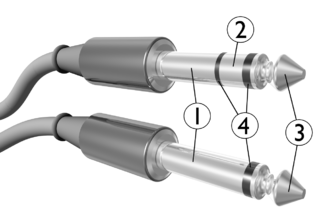
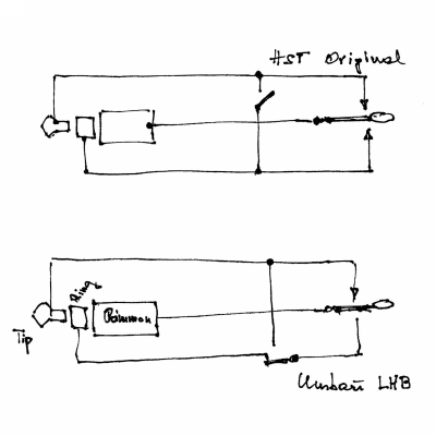
So, after wrapping my head around this and getting in touch with my CW Elmer, Heinz OE3LHB, he told me he’d gone through that before, with his first-generation Begali HST and his Yaesu TRX. He sent me this sketch of the original wiring and the sketch of the wiring that is needed for sideswiper mode to work on those TRX that expect a mono jack on straight keys:
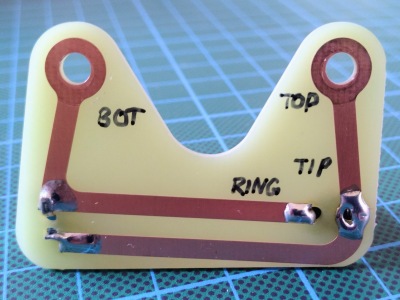
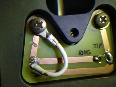
So, instead of shorting upper and lower contact, both contacts should be routed to the tip. If you look closely, you notice that the 2-pin on/off switch has to be replaced by a 3-pin on/on switch. The 1st-gen HST came without wiring, the YL/OM had to do the wiring themselves, so, this mod wasn’t overly complicated to do. But the HST III comes with the wiring realized on a PCB:
The procedure to implement the desired wiring is:
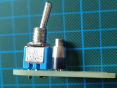
- Find a 3-pin on/on switch with the exact same size specs of the original switch. I soldered the original switch out and made measurements with a caliper, it should resemble a 5×8 mm rectangle when viewed from the top. I found a matching switch here.
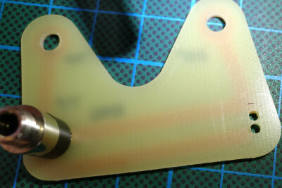
- Make a third hole to be able to fit the third pin of the switch through the PCB.
Switch removed, placement of the third hole marked, which will lead right through the conductor path - Place the new switch on the PCB and screw the PCB back in. Only then start soldering the outer pins of the switch to the respective conductor paths. Take care to leave the middle pin isolated from those. (Maybe you should do #5 before this.)
- Disconnect the switch from the bottom contact (BOT) by scratching through the conductor path. That is, only keep contact with the RING.
- Connect the middle pin of the switch to the bottom contact (BOT) using isolated wire and a soldering eyelet. (You could also paint a conductor path at the left border of the PCB, if you can do this.)
By this, sideswiper mode finally works. I sent this mod to Bruna Begali and explained why we needed to do that, but I didn’t receive a reply. Maybe they use TRX that work with the original wiring, or that key is rarely used in sideswiper mode. I never use it as a sideswiper anyway, but at least I restored that option for me.
Friday, January 31. 2020
Construction report QRP-Labs.com 50W PA

In June last year, when I talked to Hans, G0UPL, ordering his QCX kit at his booth at the Ham Radio fair in Friedrichshafen, he mentioned that there would be a 50 W PA kit coming out soon, and that stuck with me. Meanwhile, I noticed indeed that QRP is just no fun when no one is answering your calls—sorry for having to say this. I like to think of this as a kind of “Law of the Conservation of Effort”: If a DX contact is established, and one of the stations is QRP, then the other one is doing all the work and effort (in terms of operating a respectable receiving antenna and/or “having to crawl into the speaker”). Well, thinking of my main goals that led me to the QCX, which were
- assembling a TRX completely on my own,
- getting a lightweight TRX, no matter its power,
- having it only support CW,
wouldn’t there be a better follow-up step than
- assembling a PA kit,
- a lightweight PA such that QRP is no longer an option (hi),
- having it only support CW (not sure about this, though, but at least it’s marketed as “the QCX PA”).
So, I kept close eyes on the QRP Labs site in the recent months for signs about that PA, and finally, at the beginning of December, Hans announced that PA on the mailing list, and only about one hour later my order was through. I was one of the lucky ones that could include his enclosure kit before it went out of stock.
QCX mods
While I waited for the kit to arrive, I had time for preparation: The QCX needed a PTT mod to be able to provide a PTT signal to the PA; this is achieved by patching a stereo jack into the circuits (plus creating an outlet in the QCX’s enclosure) and adding a pull-up resistor. I also flashed the latest firmware release using an Arduino Uno as programming device, which might be a topic for a different blog post. The harder question to answer was how to get a cheap but still qualitative 20 V 5 A power supply for the PA. Luckily, I already possessed the Lenovo UltraSlim 90 W (20 V 4.5 A) notebook travel power adapter, which even included the option to use a wall socket or a standard automobile 12 V plug. Therefore, I could even go from a standard 12 V lead-acid battery. I only needed a non-standard DC barrel adapter, which took some extra time to arrive. While I was at it, I purchased a 3S LiPo battery pack with nominal 11.1 V to power the QCX itself with something lightweight; note that I measured up to 13.1 V fully charged, so using a fresh 4S pack might fry the QCX.
The PA kit arrived after Christmas, and I was again looking forward to the assembly process, which promised to be not as lengthy as that for the QCX. It took me about ten hours nonetheless, mainly due to assuming errors where there had been none. I will now go over some specialties that I had encountered during the assembly.
Continue reading "Construction report QRP-Labs.com 50W PA"
Friday, September 27. 2019
Construction report QRP-Labs.com QCX-40

(This time in English, as there isn’t that much mechanical vocabulary involved that I was too lazy to look up in the dictionary, as was the case with my report about building the folding hex-beam. ![]() )
)
Considering my root motivations that made me involved with ham radio, there were three main points I wanted to fulfill:
- Build (but not necessarily design) a TRX completely by myself to gain some making skills, and understand at least the main part of how that HF circuits work,
- Get a small and lightweight TRX for portable operations, no matter if that meant QRP or not,
- Have it only support CW to force myself using CW exclusively on the air, which is a requirement that became relevant to me when I started learning CW. (In addition, CW would help compensate for the QRP constraint.)
So, walking down the aisles of the HAM RADIO fair in Friedrichshafen this June, besides fetching my shiny new Begali morse key, I was looking around for the CW TRX kits, designed to be soldered and assembled by their new owners themselves. The first one I saw (model name skipped here deliberately) was already promising, but it lost against the QCX: The QCX is younger, it has less SMD components (only two, and they are already soldered onto the PCB), and it was way(!) cheaper, despite comparable features. The only advantage of the expensive kit was that one could change the band by replacing a small band-specific module. On the other hand, although the QCX is a one-bander only, with a price tag of only EUR 44.00, one could simply build another QCX for that other desired band. I decided to go for the 40 m variant, having the coming winter season in mind.
As a beginner, it was also important for me to be able to tune the finalized TRX without any troubleshooting that requires advanced electronics know-how, involving signal generators and oscilloscopes. The QCX fulfills this by offering a built-in signal generator and an initial tuning routine that YL/OM follows by adjusting some trimmers while watching an amplitude bar on the display.
Assembly
When the kit arrived with all its component parts, I was really looking forward to the assembly process. And indeed, it was a lot of fun, boosting my soldering skills with each installed component and checking each step with a jeweller’s loupe. The whole assembly took me about 20 hours, spread accross several tinkering sessions:
| Duration | Total | Tasks |
|---|---|---|
| 2:00 | 2:00 | First 5 ICs |
| 3:00 | 5:00 | 3 ICs, 26 capacitors |
| 1:45 | 6:45 | 21 capacitors, 4 diodes |
| 2:30 | 9:15 | 1 diode, 2 crystals, 28 resistors |
| 2:00 | 11:15 | 23 resistors |
| 1:45 | 13:00 | 9 resistors, 4 trimmers, 2 small inductors, 4 elcos |
| 1:45 | 14:45 | 1 elco, 1 trimmer capacitor, 7 transistors, headers & test points, power connector, voltage regulator |
| 1:45 | 16:30 | Wind and install 4 toroids |
| 1:20 | 17:50 | Wind and install transformer |
| 1:30 | 19:20 | BNC & stereo connectors, buttons, rotary encoder, microswitch, gain control, spacers, LCD module—first power-up |
| 0:30 | 19:50 | Tuning |
Continue reading "Construction report QRP-Labs.com QCX-40"
Tuesday, June 4. 2019
Baubericht FoldingAntennas.com Hex-Beam

Ich habe zwar angekündigt, den Baufortschritt zu dokumentieren, bin dann aber doch nicht so erpicht darauf gewesen. Eher kann ich also rückblickend und vom Fazit berichten, denn Berichte wie der von diesem OM z.B. sind weitaus detaillierter. Alles in allem lässt sich sagen, dass die Anleitung präzise auf alle Schritte eingeht; es ist hilfreich, alles ein- oder zweimal genau durchzulesen, bevor OM/YL mit dem ersten Arbeitsschritt beginnt. Anfangs musste ich auf die Definition von Begriffen achten, wie: Was ist ein Element (= 2 Strahlerhälften + 2 Abstandsseile + 1 Reflektor), ein Elementhalter (= „Dreizack“ auf den Spreizern), eine Universalklemme (= Verbindung von Drähten und Abstandseilen zu einem Element)? Sehr erfreulich war, dass das Tragrohr schon komplett fertig geliefert wurde, das hätte nochmal Zeit gekostet; das Tragrohr ist ein Koaxialfeeder, bestehend aus einem äußeren Rundrohr und einem inneren Vierkantrohr, die voneinander isoliert sind. Ein Ende aller Strahler ist elektrisch mit dem Außenrohr verbunden, das jeweils andere Ende symmetrisch dazu mit dem Innenrohr, und zwar anhand einer durchs Außenrohr durch führenden Schraube.
Der Zusammenbau benötigt seine Zeit, hat aber Spaß gemacht und war ohne besondere Überraschungen. Ich habe dafür inkl. Feinabstimmung allerdings 19(!) Arbeitsstunden benötigt, aufgeteilt auf mehrere Bastelabende bzw. -wochenenden. So ging ich vor:
| Dauer | Gesamt | Tätigkeiten |
|---|---|---|
| 2:45 | 2:45 | Erstes Auspacken, Spritzgussteile ausschneiden |
| 2:30 | 5:15 | Spreizermontage, lange Tragseile zuschneiden |
| 1:00 | 6:15 | Kurze Tragseile zuschneiden, Beginn Strahler zuschneiden |
| 3:00 | 9:15 | 12 radiale Tragseile auf Spreizer, Strahler zuschneiden |
| 4:30 | 13:45 | Reflektoren & Abstandsseile zuschneiden, Element-Zusammenbau |
| 1:15 | 15:00 | 2 horizontale Tragseile + 10 m-Element montieren, alle Halter aufklipsen |
| 1:00 | 16:00 | 12–20 m Elemente montieren |
| 3:00 | 19:00 | Feintuning |
Entgegen der Anleitung wollte ich die Schrauben nicht mit dem Hammer in die Verbinder der Spreizer hineintreiben, weil ich hierfür zu viel Kraft aufwenden hätte müssen und um das Material gefürchtet habe; die Öffnung war einfach zu eng. Ich habe sie stattdessen anhand einer Sicherungsmutter auf der Gegenseite schraubend hineingezogen. Selbiges dann beim Anbringen der innersten Spreizersegmente am Tragrohr: Das beschriebene „Eindrücken“ der Schrauben war mir schlicht nicht möglich.
Das Aufklipsen der Elementhalter auf die Fiberglasspreizer ging mit Hilfe einer Wasserpumpenzange ebenso ohne Kraftausdrücke, äh, -aufwand.
Continue reading "Baubericht FoldingAntennas.com Hex-Beam"
Wednesday, March 20. 2019
Mein erster Alumast: Stabilisierungsmaßnahmen

Stativ-Tüftelei
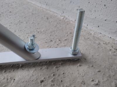
Mein Stativ für meinen 10 m Alu-Teleskopmast hat auf mich anfangs ja leider etwas wackelig gewirkt: Die Unterschenkel werden bei SpiderBeam nicht so effektiv wie etwa die WiMo-Stativfüße mit Schellen festgeklemmt, sondern nur mit einer Schraube arretiert, die senkrecht auf die Oberfläche quetscht – und zwar nur mit dem blanken Ende der Schraube, ohne besonderen „Klemmfuß“. Die Idee, Bohrungen vorzunehmen, damit die Schraube etwas in das Unterschenkelrohr hinein versenkt werden kann, war offenbar genau richtig: Anhand einer 7,5 mm-Bohrung lässt sich die M8-Schraube gerade so weit in das Rohr versenken, dass es sowohl weder hinein noch hinaus rutschen kann als auch sehr gut festgeklemmt wird. Dadurch konnte ich auch die Unterschenkel recht weit ausfahren – das Stativ ist nun 94 cm hoch.
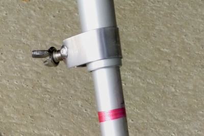
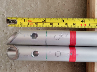
Die Idee der Stativbeschwerung, die ich von einem OM aufgegriffen habe, um eine Mastabspannung umgehen zu können, habe ich gleich mit der Möglichkeit zum Montieren eines Rotors auf Streben an den Stativfüßen verknüpft, wie sie SpiderBeam selbst anbietet: Ich habe mir aus dem Baumarkt zwei Alustreben mit Maßen 20×6×2000 mm besorgt und in der Mitte getrennt. Sie werden an den Stativfüßen angeschraubt und treffen sich etwa rautenförmig beim Mastfuß. Gemäß Manual des geplanten Rotors (Yaesu G-450C) sitzen die vier Befestigungspunkte an den Ecken eines Quadrats mit 84 mm Seitenlänge.
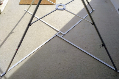
Die Streben beim Mastfuß jetzt schon so zu verschrauben, kommt der Stabilisierung auf weitere Weise zu Gute: Die Füße haben durch die weitere Verspreizung nun kaum noch Bewegungsspielraum, und zusätzlich wird das Gewicht von Mast und Antenne auf das Stativ mit übertragen – denn wenn sich der Mast frei drehen soll, steht das Stativ ansonsten nur für sich alleine da.
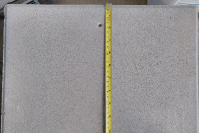
Die Alustreben am Boden sind also je 1 m lang. Gemäß Pythagoras projiziert sich ein 125 cm langes Stativbein, das im Winkel von 45 ° steht, mit einer Länge von 88,4 cm auf die Grundfläche. Ein paar Zentimeter mehr in die Mitte gerückt, damit sich eine schöne Raute für den Rotor bildet, und schon bleiben außerhalb des Stativfußes nur mehr ca. 5 cm von den Streben übrig. Genau die habe ich aber noch genutzt, um die vier Gehwegplatten lieber außerhalb statt innerhalb der Stativfläche zu platzieren – die Gewichtsverteilung kommt wiederum der Standfestigkeit zu Gute. Ich habe mit mir gerungen und mich dann doch für die kleineren 40×40×5 cm Gehwegplatten à ca. 17 kg entschieden.
Mast-Tüftelei
Ursprünglich hat mich auch das mühsame Ausfahren des Mastes beschäftigt. Nach etwas Herumprobieren wurde mir klar, dass bei eingefahrenem Zustand eine Schelle nicht nur das nächste, sondern auch das übernächste Mastsegment etwas festklemmt! Sobald man also auch die Schelle darunter etwas lockert, lässt sich das Segment ohne große Reibung ausfahren. Warum steht sowas nicht in der Anleitung, die überdies dem Mast gar nicht beiliegt?
Mich hat etwas irritiert, dass die Endmarkierung des dünnsten Segments (30 mm Außendurchmesser) nur noch 6 cm Einklemmlänge übrig lässt, also nur den doppelten Außendurchmesser. Ich habe kurzerhand alle Rohre einmal entnommen und nachgemessen, wo die Endmarkierungen platziert sind: Es ist bei allen der doppelte Außendurchmesser, beim vorletzten (65 mm breiten) Segment also 13 cm Einklemmlänge. Das ist dann eigentlich eh okay – ich hatte anfangs befürchtet, wenn ich mit einem bisschen zu heftigen Ruck ausziehe, plötzlich versehentlich das ganze Segment herauszuziehen und somit einen „Super-QAU“ zu verursachen. (QAU = “I am about to jettison fuel”. ![]() ) Das ist umso kritischer, je weiter der Mast schon hochgeschoben ist, doch wachsen diese Endmarkerungen eh im richtigen Maße mit. Akribisch habe ich mir berechnet, dass der Mast dann 9,9 m hoch ist, wenn man genau bis zu den Endmarkierungen auszieht. Hält man den anderswo empfohlenen dreifachen Rohrdurchmesser als Einklemmlänge ein, ist er nur mehr 9,5 m hoch, aber umso stabiler. Ich habe mir zusätzliche Markierungen dafür gemacht, auch um eine „Ankündigung“ der Endmarkierung zu sehen. Prinzipiell werde ich den Mast nur mit rutschfesten Arbeitshandschuhen handhaben.
) Das ist umso kritischer, je weiter der Mast schon hochgeschoben ist, doch wachsen diese Endmarkerungen eh im richtigen Maße mit. Akribisch habe ich mir berechnet, dass der Mast dann 9,9 m hoch ist, wenn man genau bis zu den Endmarkierungen auszieht. Hält man den anderswo empfohlenen dreifachen Rohrdurchmesser als Einklemmlänge ein, ist er nur mehr 9,5 m hoch, aber umso stabiler. Ich habe mir zusätzliche Markierungen dafür gemacht, auch um eine „Ankündigung“ der Endmarkierung zu sehen. Prinzipiell werde ich den Mast nur mit rutschfesten Arbeitshandschuhen handhaben.
Eigentlich wollte ich noch die M10 Innensechskant-Schrauben an den Schellen durch Knebelschrauben (nicht Klemmhebel und nicht Sternschrauben) ersetzen, was die Bedienung erleichtern sowie beschleunigen soll. Da diese aber weder leicht noch günstig zu besorgen sind, werde ich mir mit einem einfachen T-Griff als Werkzeug behelfen.
Koax-Tüftelei
Hier habe ich nur die Entscheidung getroffen, das 25 m Koax zu einem reinen Fieldday-Kabel zu deklarieren und nochmal 15 m zu besorgen. Ich werde davon nämlich immer nur ein paar Zentimeter durch die erwähnte Öffnung ins Shack führen und dort an ein anderes Kabel anstecken, das fix am Rig steckt; ja, diese Verbindung erzeugt zusätzliche Dämpfung. Ich muss dann jedenfalls immer nur mehr 15 m Kabel handhaben und werde es wie geplant nur wie ein Kletterseil aufnehmen, nicht einrollen, was einiges an Zeit sparen sollte.
Tu du
Wenn ich Stativ und Mast wie beschrieben aufbaue und ordentlich gegen den Mast drücke, überzeugt mich die Gegenkraft, dass das Ganze auch einen moderaten Wind aushält – der Mast darf sich halt nicht zu sehr biegen, weil sich die Segmente verziehen könnten und er evtl. nicht mehr eingefahren werden kann. Ich will aber ohnehin nicht bei stärkerem Wind aufbauen, zumindest nicht ohne Abspannungen zu verwenden.
Noch im März will ich den Folding-Hexbeam besorgen, damit ich ihn an unserem Fieldday Ende April verwenden kann, an dem ich erstmals teilnehme. Den Zusammenbau werde ich dokumentieren.
Tuesday, March 12. 2019
Mein erster Alumast: Gemischte Gefühle

Ich habe mir einen 10 m hohen Alu-Teleskopmast von SpiderBeam gekauft, inklusive Alu-Stativ mit vier 1,2 m langen Beinen. Plan ist, dass der demnächst einen zusammenfaltbaren Multiband-Hexbeam für die Bänder von 20–10 m trägt. Rahmenbedingung ist bei mir, dass ich vor meinem Shack den Mast jedesmal alleine auf- und wieder abbauen muss. Zusätzlich kann ich keine Heringe o.ä. in den Boden rammen. Als ich die Mastkonstruktion das erste Mal aufgestellt habe, haben mir ein paar Dinge Kopfzerbrechen bereitet:
- Das Stativ wirkt nicht sonderlich stabil. Ich habe allerdings ohnehin zuvor die Aussage gelesen, dass das Stativ nicht mehr viel hilft, sobald der Mast 4–5 m ausgefahren ist. Misstrauen weckt in mir die Arretierung der Stativbeine für die Nivellierung: Da werden die inneren Beinrohre einfach anhand einer Schraube festgequetscht. Das kommt mir nicht so vor, als würden die Beine eine moderate Seitenhebelkraft (bei Windeinwirkung auf den Mast) stemmen können, das dünnere Beinrohr könnte in das Überrohr rutschen und der Mast umkippen. Ich habe überlegt, Bohrungen zu machen, damit die Schrauben ins Beinrohr versenkt werden können und nicht einfach nur auf die Oberfläche quetschen. Das Nivellieren ist dann halt nicht mehr sehr flexibel. (Idee: Die dünneren Beinrohre ein bisschen über die Sicherheitsmarkierung hinaus ausfahren und auf diesem Niveau die Bohrungen anbringen, dadurch wird das Stativ zugleich auch minimal höher.)
- Der Mast selbst lässt sich nur mit Kraftaufwand ausfahren. Ich hebe teilweise das untere Mastrohr mitsamt dem Stativ an! Ich muss also das Stativ mit meinen Beinen am Boden halten und muss dann unter Hin- und Herdrehen die Segmente ausziehen. Das ist schon ohne Antenne am Mastkopf mühsam! Soll das wirklich so sein? Lassen sich die Rohre nach einiger Zeit besser ausfahren? Ich habe Videos gesehen, da sieht das viel eleganter aus. Der Mast ist eingefahren eh nur 1,35 m hoch, aber mit meiner geringen Körpergröße ist auch das nicht auf Hüfthöhe. Idee: Einen Schemel oder eine kleine Trittleiter verwenden, damit der Zugpunkt etwas weiter unten liegt. (Tipp eines OM: Teflonspray als Gleithilfe, vorsichtig dosiert. Zusätzliche Idee: Lamellen etwas auseinander biegen.)
- Ich wollte eigentlich ohne Mastabspannungen auskommen, um Zeit zu sparen, und dem Stativ nur „Elefantenfüße“ aus Gehwegplatten verpassen. Es sieht so aus, als müsste ich das alleine schon wegen des störrischen Ausfahrens machen, um das Stativ am Boden halten zu können. Das Gewicht alleine lässt sich ja recht einfach erreichen. Ich muss aber, wie gesagt, noch dafür sorgen, dass die Stativbeine eine seitliche Kraft besser stemmen können. Was nützt ein schweres Stativ, das einfach die Beine einzieht?
- Alternativ bleibt nur die Abspannung des Mastes. Aber genau nach Westen, der hiesigen Hauptwindrichtung, ist bei mir keine Möglichkeit, ein Seil am Boden zu verankern. Ich habe mir einen Betonschirmständer gekauft, der sich als viel, viel zu schwer erweist und alleine schlicht nicht manövrierbar ist! Ich habe mir eine Lastkarre besorgt, doch ist diese zu schwachbrüstig, um das Ungetüm zu heben. Als weiteres Transporthindernis ist der Boden, auf dem ich aufbaue, auch nicht glatt, sondern ein verdichtetes Granulat. Mir fehlt also noch eine Möglichkeit, eine Abspannung nach Westen vorzunehmen; nach Osten habe ich immerhin Metallzaunpfähle. (Idee: Einen horizontalen Träger oder eine Art fünftes Stativbein vom Zaunpfahl zum Mast, nur müsste das wegen des Drehradius des Hexbeams ziemlich lang sein.)
- Die 25 m Koaxkabel, die ich mir angeschafft habe, erweisen sich als sehr störrisch auszulegen, obwohl es eh nur 7 mm dick ist. Ich kann es nicht einfach zusammengerollt liegen lassen und das Kabel an mich heranziehen, weil sich dann Schlaufen („Krangel“) bilden, die sich zusammenziehen und so einen zerstörerisch geringen Biegungsradius erzeugen. Ich muss es also erst dediziert komplett ausrollen. Ca. 6 m davon muss ich von außen durch eine kleine Öffnung in die Garage führen, in der mein Shack ist, damit ich das Garagentor schließen kann; es wäre ja Unsinn, ca. 14 m von innen durch die Öffnung hinauszuführen. Damit addiert sich auch dieser Aufwand zur Zeit hinzu, die ich brauche. (Idee: Das Koax wie ein Kletterseil schlangenförmig aufnehmen, nicht einrollen; so ließe es sich dann gut entnehmen bzw. überhaupt auswerfen. Oder ich verwende eine Kabeltrommel – da sind aber nicht beide Enden unabhängig abrollbar; ich müsste was mit einer UHF-Buchse an der Trommel tüfteln.)
Schätzen wir mal, was da in dem Ablauf immer zu tun ist:
- Stativ mitsamt eingefahrenem Mast hinausstellen – ca. 1 Minute
- Vier Gehwegplatten à ca. 18–28 kg hinauskarren und auf die (noch geplanten) Streben an den Stativbeinen legen (durch eine Stiftdurchführung) – ca. 2–4 Minuten
- Hexbeam am Mast anbringen und vollständig entfalten – ca. 5 Minuten (Ist das zu optimistisch? Ich muss ihn nämlich nicht immer komplett zusammenfalten/verpacken.)
- Koaxkabel ausrollen, einen Teil davon durch eine Öffnung führen, an TRX und Antenne (inkl. Zugentlastung) anstecken – ca. 3–5 Minuten
- Mast ausfahren – ca. 4 Minuten für 8 Segmente, also ca. 30 Sekunden pro Segment, inkl. Auf- und Zuschrauben der Schellen.
Damit brauche ich immer ca. 15–20 Minuten Aufbau sowie Abbau – denn die Schätzung könnte zu optimistisch sein. Daraus ergibt sich, dass ich das nicht einfach jeden Abend machen will, und ich muss dann auch ca. 2–3 Stunden QRV sein, damit sich diese Mühe auch lohnt. Gesamtzeitaufwand vor Ort also 2½–3½ Stunden, davon 18–25 % Vor- und Nachbereitung. Tja, ist halt so. Immerhin habe ich dann eine bessere Antenne, als ich es mir je erträumt hätte, denn selbst eine „einfache“, gut 7 m hohe Mehrband-Vertical war an meinem QTH nicht als Permanentinstallation möglich. Unter Umständen werde ich diesen Aufwand nur an Freitagabenden oder am Wochenende treiben. Während der Woche spare ich Zeit durch Verwendung der einfachen Teleskop-Vertical oder der endgespeisten Drahtantenne.
In der Wintersaison sollte der Aufwand nicht gar so hoch sein, wenn abends ohnehin nur die unteren Bänder offen sind und ich den Hexbeam somit nicht verwenden kann. Ich würde dann entweder einfach die Endgespeiste hochfahren, was 5 Minuten „Ausfalten“ spart, oder, gemäß Idee, eine Monoband C-Pole für 40 m, die sich mit dem Masthochfahren entfaltet; letztere wäre allerdings vermutlich nur an einem nichtleitenden Mast möglich.
Einige der oben genannten Ideen habe ich bereits umgesetzt und so die Befürchtungen neutralisiert – darüber werde ich separat berichten.
About
Calendar
| Mon | Tue | Wed | Thu | Fri | Sat | Sun |
|---|---|---|---|---|---|---|
| ← Back | January '26 | |||||
| 1 | 2 | 3 | 4 | |||
| 5 | 6 | 7 | 8 | 9 | 10 | 11 |
| 12 | 13 | 14 | 15 | 16 | 17 | 18 |
| 19 | 20 | 21 | 22 | 23 | 24 | 25 |
| 26 | 27 | 28 | 29 | 30 | 31 | |
