Friday, July 14. 2023
Construction report QRP-Labs.com QMX

In 2019, I decided to build the QCX monoband-TRX to have a lightweight TRX that serves a radio band that should be okay to use throughout the year, 40 m. I was still building up a basic ham radio gear “portfolio” and didn’t own HF antennas that could specifically be used for SOTA. I could be using an end-fed for SOTA, I thought, but didn’t own a compact telescopic mast to be able to lift the wire up on a summit. I do own the MFJ-1979 telescopic vertical, though, that I sometimes use when operating HF from the car. But, it is only resonant on 20 m and up. For 40 m, I’d have to add the extra coil. The MFJ-1979 alone is already quite heavy, though, even more together with the coil. So, I got the idea of buying the QCX-mini for 20 m, which would reduce some weight for both TRX and ANT, and 20 m would raise chances for DX during the summer season when I intended to roam summits. I’d still need to carry a small tripod, though, for the vertical.
Then came the QMX, the same size as the QCX-mini, but a multi-bander for 80/60/40/30/20 m! This would be the solution, and I purchased one kit at the QRP-Labs booth at the HAM RADIO fair in Friedrichshafen last month, right after walking through the doors.
Assembly promised to be not so adventurous as that of the QCX anymore, as all resistors, several capacitors and all ICs were already SMD-soldered to the PCB. I still had to wind the filters and transformers, though, and add the other components. A funny thing to read in the assembly manual was, that Hans somehow got aware that left-handers wind mirrored toroids. I mentioned this in my QCX construction report, the toroids end up a bit skewed on the PCB. Since the QMX PCB is much more compact, this would be an important thing to keep in mind. To achieve the same result, I also wound the toroids counter-clockwise, left-handed, but starting at the 12 o’clock position, not at 6 o’clock, like the right-handers do.
This was already my assembly report!  I’ll only mention some stumbling blocks I experienced.
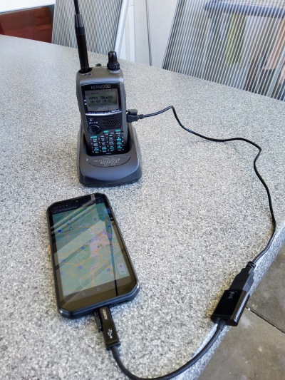
First, it is obvious that the assembly manual is in an early stage. While there aren’t any real errors in it, it can be a bit confusing due to sections of the QDX assembly manual having been pasted in, obviously. So, I got the first shock when turning on the TRX for the first time, it staid dully dark. But, reading a bit closer into different sections, I read that the QMX initially starts in firmware update mode, that is, it was simply just a USB thumb drive at that point, nothing more! The picture in the manual showed a happily glowing display with a frequency reading, though. I connected the QMX to the notebook, pushed the power button once more, and voilà, a new drive appeared! I could successfully copy the firmware file to it.
When I measured power output into a dummy load, I could read about 4 watts when feeding the QMX about 13 volts from a LiFePO4 battery. I didn’t do any alignment, because there isn’t a description of this procedure yet. A thing that disturbed me was that extremely loud noise in the headphones on key release. I inspected the PCB closely, but didn’t find anything suspicious. So, I went to the QRP-Labs group. There, I learnt that the QMX offers a USB terminal console with a configuration menu! That’s not too surprising, after all, as the QMX is an SDR-based TRX. In the config menu, I went to Band Configuration and set the “TX/RX param 2” value from “0” to “1”, and a reboot had this issue resolved!
Later, there was a topic discussed in the group about the QMX being quite deaf at 20 m. Hans proposed some solutions, and I went with his recommended solution #2. That means: It is enough to wind the 20 m (19 windings) and 30 m (11 windings) sections onto L401. Have the windings spread out such that the 20 m tap goes one place further into the 30 m hole, and the 30 m tap to the 40 m hole. Then patch the 40 m to the 80 m hole, and do the configuration changes for the BPF. (This is already adapted in version 1.00f of the manual.) The BPF frequency sweep diagram looks promising; this is another awesome feature of the terminal console.
When using the optional enclosure, it is important that the control PCB can pass through the outlet in the display PCB easily. Therefore, you should take care that all protruding elements are honed away, just as mentioned in the manual. You can carefully wiggle on the controls to help it pass through. And that reminds me of another stumbling block: One following day, the TRX suddenly didn’t turn on anymore. I removed the enclosure, put apart the PCBs and connected them again, then the TRX turned on again. I suspect that the left control’s outer hull was touching the DC socket’s back. Therefore, be sure to put some insulating tape over the control’s left side and/or the DC socket’s back. Also, when soldering the controls themselves, don’t use too much solder. Initially, I made another short-circuit that disabled volume control.
Apropos volume control, that one was difficult to tame. Sidetone volume always was too loud, I had to turn the volume down before keying and up afterwards. Also, turning the left control didn’t really turn the RX volume down counter-clockwise or up clockwise. Rather, the volume was cycling between a few different levels when the knob was turned into one direction. I seemed to have tamed this behavior by either insulating the control from the DC socket (as described above) or by setting sidetone volume to 005 in the menu.
An interesting feature of the QMX is the possibility of new functions coming with later firmware updates. For now, the decoder doesn’t seem to be working (which I see as feature solely for non-telegraphist/non-ham spectators), and the built-in mic has no function yet (and I’ll never use it anyway).
I want to use the QMX to finally do my first SOTA activations later this month. At the HAM RADIO fair, I also stumbled upon another solution to save weight for ANT and tripod: The CleverSticks, which are hiking sticks that can be transformed into a tripod, for use with a camera or an ANT, namely the Elecraft AX-2 telescopic vertical. It is shorter and smaller than the MFJ-1979, but the raised location of a summit (plus doing CW) should be able to compensate for that. Since one would carry hiking sticks anyway, there is no extra weight of a tripod at all. The last piece of the puzzle finally was the key: I purchased the Palm Radio Single paddle at the fair. This is the gear I’ll be using, and I will find out if it serves me well.
Friday, March 3. 2023
Telegrafische Übertragungsmitteilung

Von: <spammer>
Betreff: TELEGRAFISCHE ÜBERTRAGUNGSMITTEILUNGSehr geehrter Begünstigter,
TELEGRAFISCHE ÜBERTRAGUNGSMITTEILUNG.
Wir benachrichtigen Sie hiermit offiziell über Ihre telegrafische Überweisung durch unsere Zahlbank, die ING Bank N.V. Vereinigtes Königreich, auf Ihr Bankkonto [...]
Die wissen genau, wie sie mich ködern können! 
Sunday, December 18. 2022
Memorable QSOs
He who does radio communication has stories to tell: During the time as an active a ham, memorable stories are accumulating. I want to document these for me before I forget the details. I’m licensed since four years now, and during the last three years I was using CW almost exclusively on the air. In this short time I was collecting (only) a few special moments which I want to share here.
Under the radar
The count and variety of HF band intruders has risen since the Russian invasion in Ukraine this year. One really annoying case are over-the-horizon radars sending in ham radio bands, as these transmissions always consume a remarkable frequency range. These radars can be recognized clearly due to their buzzing sound and tremendous signal strength, so it is pointless to attempt anything over these blockades. (Some hams however try to deliberately disturb these transmissions, but that’s comparable to a bird yelling at a bulldozer.) This April I was in the middle of a QSO with a Briton on the 30 m band, when suddenly a radar burst in, with us being exactly surrounded by noise. It kicked in during my transmission. I was puzzled when I heard it (I use full break-in to receive between my characters), but I had no choice other than continuing my message. It would be hopeless, I thought, to catch any response from my fellow. But, alas, his CW beeps could be clearly distinguished from the buzzing radar noise! I quickly launched Audacity and recorded the rest of our QSO. Try to hear for yourself: (Warning: Noisy!)
(I tried to enhance the audio later by filtering around 700 Hz, but every attempt made it worse. CW can be distinguished best from the full radar spectrum, interestingly.) I also made a picture of my SDR receiver’s waterfall diagram after one of my transmissions. You cannot make out my friend’s signal visually, though:

So, despite this heavy QRM, we could continue and finalize our conversation, thanks to the powers of morse telegraphy.
QSL via e-mail
I really enjoy exchanging paper QSL cards, especially receiving them from DXpeditions or DX stations. I decorate my shack’s wall with the most picturesque of them. While it makes past QSOs special by having them materialized in paper form, these processes are mostly automated: The prints are generated out of the log program and a common greeting is added. One kind of extra mile and appreciation of a recent contact, however, is an almost immediate personal e-mail after the QSO. For example, I answered two Brits which appeared to be beginners and to have one of their first HF sessions in each other’s company. I had a nice QRS QSO with each of them, and both of them thanked me kindly via e-mail soon after. I also received an e-mail from a young Indonesian after our QSO on 10 m this April.
One very thankful e-mail was again from England. Usually, the weaker signals are most interesting: Is it from far away? Is the station using low power and might thus not get plenty of answers? Will they be able to hear me at all? Well, it turned out, he was QRPP, sending with only 1 W, but easily bridged the 1200 km between us. He later sent me a picture of his setup on the kitchen table, where his TRX was powered by a 9 V battery. I was almost embarassed by me blowing out 100 W. It might have been interesting if I could have turned my output down to 5 W and still have this QSO.
Easy DX
We are three years into the current solar cycle with DX conditions having clearly improved this year’s summer term. Previously, I operated from a garage where I could use my hex beam in a portable-like setup. Since the pandemic I mostly operate from home, using home-made full-size wire loops for 20 m and 30 m and a home-made end-fed for the lower bands. These aren’t directional antennas, though, but I can use them more often, and they are good enough—good enough to have remarkable DX stations reply to my CQ calls: This May I did an unexpectant CQ call on 20 m, and then someone replied with a crystal clear signal... from Indonesia! We had a very nice QSO with hardly any fading. Sadly, I don’t have a recording. I should systematically record my sessions from now on.
Return at first attempt
This is actually just a side note what difference a directional antenna makes compared to a long wire. What positively surprised me during my first hours with my hex beam continued to be awesome whenever I used it: Often, when I joined the pile-up for a DXpedition or DX station with my 100 W rig, only one or a few calls were necessary on my side to already hear the DX station repeat my call! This was already the case when I did SSB. But also my wire loops enabled me to experience these first-attempt successes, since the solar condx are improving.
Getting licensed close to a solar minimum has the advantage of positive surprises for years to come.
Monday, November 28. 2022
OE Amateurfunk-Rufzeichen-Deltas in eigenem Feed
Meine automatisierten Blogposts über die aktuellsten Änderungen im Bestand der österreichischen Amateurfunk-Rufzeichen haben das SNR gegenüber meinen eigentlichen Amateurfunk-Postings dezimiert. Daher sind diese Änderungen nur mehr über den Hauptfeed dieses Blogs bzw. über die eigene Kategorie OE Ham Calls auffindbar, nicht mehr über die allgemeinere Ham Radio Kategorie.
Das ist mir dann hoffentlich ein Antrieb, wieder mehr zu diesen Themen aktiv zu sein.
Wednesday, September 7. 2022
Kenwood TH-D72 on APRSDroid

I managed to use APRSDroid (v1.6.2b) on a BlackView BV9900pro (Android 10) with a Kenwood TH-D72E TRX. It works, with a few caveats.
The HT itself needs to be set to the same APRS settings as the TM-D710, which are:
- Com Port
- Baud Rate (screen 330): 9600 bps
- Input (331): Off
- Output (332): Waypoint
- Waypoint
- Format (340): KENWOOD
- Length (341): 9-Char
- Output (342): All
One difference to the TM-D710 is that the TH-D72 has got native USB. Therefore, I also set PC Port Output (screen 350) to On.
I connected the HT with a Mini-USB cable to a USB-OTG adapter which had a Micro-USB plug. Using a USB-C adapter, I connected it to the BV9900pro. A simple USB OTG app didn’t list any USB devices connected, though. I noticed I had to switch on “OTG data exchange” in Settings > System. Now APRSDroid showed a USB device connected, and I could start tracking.
I noticed two caveats, which might be completely the smartphone’s fault. (It performs aggressive internal task killing which can’t even be entirely neutralized by rooting and modding.) Note that the “OTG data exchange” setting shows a description that it would be switched off when unused for 15 minutes. In my case, it switches off anyway, even if the phone’s screen is on and APRSDroid is tracking. The second issue is that when I switch to map mode while the USB connection is on, the app freezes and is cumbersome to stop and restart. I always have to switch off OTG first, then study the map, switch back to list view, activate OTG and start tracking again.
Additional thoughts: The TH-D72 is an aging device. It was introduced in 2010, I bought it new when I got licensed in 2018, and it was discontinued soon after. It is still the only device available [besides the TH-D74] that offers an all-in-one solution for Packet/APRS/GPS that also works perfectly from Linux and Android. Although I’m a ham for a little time now, it always puzzles me how information can be so inaccessible to newbies: Only recently I managed to use Packet Radio at 1200 baud to
- send WinLink messages directly from the HT (called APRSLink),
- send ordinary e-mails directly from the HT,
- receive(!) ordinary e-mails directly on the HT, via APRS radio (what is endgame-awesome), and
- use AX.25 on a Linux machine to connect to WinLink via a Packet node,
all of which are actually old-school meanwhile. It also took me four years to figure out APRS works directly between the HT and a smartphone or tablet. At least I established these options for me now.
The TM-D710 disappeared from the market last year, and I was caught by surprise. After months of searching I could finally buy one used. This mobile TRX also offers APRS on-board which can be directly accessed from Linux.
Sunday, August 8. 2021
Messing with CQRLOG data behind the application

Currently, in CQRLOG 2.5.1 of Ubuntu 21.04, QSL export for label printing is broken due to a FreePascal bug:
TRegExpr exec: empty input string.
Version 2.5.2 contains a fix, though. Now I had the choice between these unpleasent options:
- Go through dependency hell by using the CQRLOG PPA for Ubuntu. This repo however has got some unresolvable dependencies. Attempts to work around these moved my system from MariaDB back to MySQL, resulting in a migration of the system database directory, what made a “downgrade” back to MariaDB another huge stumbling block. Luckily, I could switch back to 2.5.1 on MariaDB again.
- Go through dependency hell by trying to compile CQRLOG from source. Either I’d have to mess with several odd development packages on my system directly, or by using a Docker container. This was a path I didn’t really want to take.
- Delay printing QSL cards for several months until Ubuntu 21.10 is out (which hopefully contains that fix).
Couldn’t I somehow work around that bug? After all, I just wanted to dump certain log entries to a CSV. This could be done using an ordinary MySQL client! And this is the procedure to do so:
Start CQRLOG, this launches a MySQL (MariaDB) server instance in the CQRLOG data directory, which is ~/.config/cqrlog/database by default, listening on port 64000. Now, simply connect to it:
Use the desired database:
Query, using the columns you usually export:
The resulting CSV is already almost in the usual format, except for the date. In Vim, I did these transformations:
etc.
As soon as I was satisfied with the result (in gLabels), I marked these QSL as sent:
Querying around in that table is also a good opportunity for one’s own statistics.
Wednesday, February 3. 2021
Restoring sideswiper mode of the Begali HST morse key
... on ham radio TRX like Yaesu or Kenwood
The Begali HST III morse key is a single-lever paddle that also has a sideswiper mode built in: By flipping a switch on the key’s base, one can operate it as a sideswiper. But why actually is that switch needed? Well, a single-lever creates electric contact on either of two sides, which have to be distinguished, because one side tells the keyer to emit dots (dits) and the other to emit dashes (dahs). That’s why a stereo jack is used to connect to a TRX, because that jack can carry those two channels. When using the single-lever as a sideswiper, though, both sides are equivalent and should simply trigger a key-down. Straight keys can be modeled using a mono jack only. So, for using the Begali HST III in sideswiper mode, both contacts have to be routed the same way, while in paddle mode, they have to stay separate. That’s what that built-in switch is for.
On my Kenwood TRX though, I was disappointed to notice that sideswiper mode of that key doesn’t work: When I plug it into the straight-key socket of my Kenwood TRX, a continuous key-down is emitted! It looks like Begali decided to make both contacts equivalent by shorting them. But thinking of the design of mono jacks, where most of the jack consists of common ground while only the tip carries the channel, that means that if that stereo jack is plugged into a mono socket, a part of the body and the tip are short-circuit, which simply means: key-down!
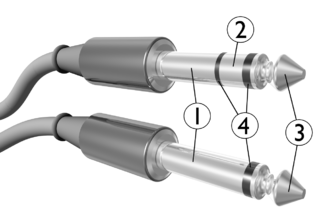
So, after wrapping my head around this and getting in touch with my CW Elmer, Heinz OE3LHB, he told me he’d gone through that before, with his first-generation Begali HST and his Yaesu TRX. He sent me this sketch of the original wiring and the sketch of the wiring that is needed for sideswiper mode to work on those TRX that expect a mono jack on straight keys:

So, instead of shorting upper and lower contact, both contacts should be routed to the tip. If you look closely, you notice that the 2-pin on/off switch has to be replaced by a 3-pin on/on switch. The 1st-gen HST came without wiring, the YL/OM had to do the wiring themselves, so, this mod wasn’t overly complicated to do. But the HST III comes with the wiring realized on a PCB:


The procedure to implement the desired wiring is:
- Find a 3-pin on/on switch with the exact same size specs of the original switch. I soldered the original switch out and made measurements with a caliper, it should resemble a 5×8 mm rectangle when viewed from the top. I found a matching switch here.
- Make a third hole to be able to fit the third pin of the switch through the PCB.

Switch removed, placement of the third hole marked, which will lead right through the conductor path - Place the new switch on the PCB and screw the PCB back in. Only then start soldering the outer pins of the switch to the respective conductor paths. Take care to leave the middle pin isolated from those. (Maybe you should do #5 before this.)
- Disconnect the switch from the bottom contact (BOT) by scratching through the conductor path. That is, only keep contact with the RING.
- Connect the middle pin of the switch to the bottom contact (BOT) using isolated wire and a soldering eyelet. (You could also paint a conductor path at the left border of the PCB, if you can do this.)


By this, sideswiper mode finally works. I sent this mod to Bruna Begali and explained why we needed to do that, but I didn’t receive a reply. Maybe they use TRX that work with the original wiring, or that key is rarely used in sideswiper mode. I never use it as a sideswiper anyway, but at least I restored that option for me.
Friday, January 31. 2020
Construction report QRP-Labs.com 50W PA
In June last year, when I talked to Hans, G0UPL, ordering his QCX kit at his booth at the Ham Radio fair in Friedrichshafen, he mentioned that there would be a 50 W PA kit coming out soon, and that stuck with me. Meanwhile, I noticed indeed that QRP is just no fun when no one is answering your calls—sorry for having to say this. I like to think of this as a kind of “Law of the Conservation of Effort”: If a DX contact is established, and one of the stations is QRP, then the other one is doing all the work and effort (in terms of operating a respectable receiving antenna and/or “having to crawl into the speaker”). Well, thinking of my main goals that led me to the QCX, which were
- assembling a TRX completely on my own,
- getting a lightweight TRX, no matter its power,
- having it only support CW,
wouldn’t there be a better follow-up step than
- assembling a PA kit,
- a lightweight PA such that QRP is no longer an option (hi),
- having it only support CW (not sure about this, though, but at least it’s marketed as “the QCX PA”).
So, I kept close eyes on the QRP Labs site in the recent months for signs about that PA, and finally, at the beginning of December, Hans announced that PA on the mailing list, and only about one hour later my order was through. I was one of the lucky ones that could include his enclosure kit before it went out of stock.
QCX mods
While I waited for the kit to arrive, I had time for preparation: The QCX needed a PTT mod to be able to provide a PTT signal to the PA; this is achieved by patching a stereo jack into the circuits (plus creating an outlet in the QCX’s enclosure) and adding a pull-up resistor. I also flashed the latest firmware release using an Arduino Uno as programming device, which might be a topic for a different blog post. The harder question to answer was how to get a cheap but still qualitative 20 V 5 A power supply for the PA. Luckily, I already possessed the Lenovo UltraSlim 90 W (20 V 4.5 A) notebook travel power adapter, which even included the option to use a wall socket or a standard automobile 12 V plug. Therefore, I could even go from a standard 12 V lead-acid battery. I only needed a non-standard DC barrel adapter, which took some extra time to arrive. While I was at it, I purchased a 3S LiPo battery pack with nominal 11.1 V to power the QCX itself with something lightweight; note that I measured up to 13.1 V fully charged, so using a fresh 4S pack might fry the QCX.
The PA kit arrived after Christmas, and I was again looking forward to the assembly process, which promised to be not as lengthy as that for the QCX. It took me about ten hours nonetheless, mainly due to assuming errors where there had been none. I will now go over some specialties that I had encountered during the assembly.
Continue reading "Construction report QRP-Labs.com 50W PA"