Friday, September 27. 2019
Construction report QRP-Labs.com QCX-40

(This time in English, as there isn’t that much mechanical vocabulary involved that I was too lazy to look up in the dictionary, as was the case with my report about building the folding hex-beam. ![]() )
)
Considering my root motivations that made me involved with ham radio, there were three main points I wanted to fulfill:
- Build (but not necessarily design) a TRX completely by myself to gain some making skills, and understand at least the main part of how that HF circuits work,
- Get a small and lightweight TRX for portable operations, no matter if that meant QRP or not,
- Have it only support CW to force myself using CW exclusively on the air, which is a requirement that became relevant to me when I started learning CW. (In addition, CW would help compensate for the QRP constraint.)
So, walking down the aisles of the HAM RADIO fair in Friedrichshafen this June, besides fetching my shiny new Begali morse key, I was looking around for the CW TRX kits, designed to be soldered and assembled by their new owners themselves. The first one I saw (model name skipped here deliberately) was already promising, but it lost against the QCX: The QCX is younger, it has less SMD components (only two, and they are already soldered onto the PCB), and it was way(!) cheaper, despite comparable features. The only advantage of the expensive kit was that one could change the band by replacing a small band-specific module. On the other hand, although the QCX is a one-bander only, with a price tag of only EUR 44.00, one could simply build another QCX for that other desired band. I decided to go for the 40 m variant, having the coming winter season in mind.
As a beginner, it was also important for me to be able to tune the finalized TRX without any troubleshooting that requires advanced electronics know-how, involving signal generators and oscilloscopes. The QCX fulfills this by offering a built-in signal generator and an initial tuning routine that YL/OM follows by adjusting some trimmers while watching an amplitude bar on the display.
Assembly
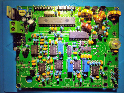
When the kit arrived with all its component parts, I was really looking forward to the assembly process. And indeed, it was a lot of fun, boosting my soldering skills with each installed component and checking each step with a jeweller’s loupe. The whole assembly took me about 20 hours, spread accross several tinkering sessions:
| Duration | Total | Tasks |
|---|---|---|
| 2:00 | 2:00 | First 5 ICs |
| 3:00 | 5:00 | 3 ICs, 26 capacitors |
| 1:45 | 6:45 | 21 capacitors, 4 diodes |
| 2:30 | 9:15 | 1 diode, 2 crystals, 28 resistors |
| 2:00 | 11:15 | 23 resistors |
| 1:45 | 13:00 | 9 resistors, 4 trimmers, 2 small inductors, 4 elcos |
| 1:45 | 14:45 | 1 elco, 1 trimmer capacitor, 7 transistors, headers & test points, power connector, voltage regulator |
| 1:45 | 16:30 | Wind and install 4 toroids |
| 1:20 | 17:50 | Wind and install transformer |
| 1:30 | 19:20 | BNC & stereo connectors, buttons, rotary encoder, microswitch, gain control, spacers, LCD module—first power-up |
| 0:30 | 19:50 | Tuning |
I made my first mistake with the very first component: At the beginning of the manual, there are some statements about using sockets for ICs versus soldering them directly onto the PCB. The designer of the kit, Hans Summers, G0UPL, decided to not use sockets—for the small ICs. I was so obsessed with soldering the ICs without using sockets that I also soldered the big ATmega328P directly onto the PCB! Only after reading some messages on the mailing list, I noticed that I should better have used the socket that came with the kit anyway. I wondered: Should I hope for the best, or would it make sense to try to unsolder it? Since I was at the very beginning of the assembly, it might have made sense to start over entirely, possibly trashing the IC and ordering a new one. I decided to hope for the best and to just continue, and indeed, at the very end, the chip had survived. Lesson learned!
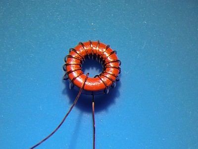
Installing the other components was quite straightforward and without any suprises. Even winding the toroids was quite fun. I decided to remove the enamel of the wires by making the solder quite hot with the iron until the enamel began bubbling away. A DVM helped me verify proper connection.
A word of caution for left-handers when winding the toroids: I, as a left-hander, held the ring core in my right hand and fiddled the wire through it with my left hand, always poking the wire through the ring from the front. That way, the windings ended up mirrored, which doesn’t matter from an electric point of view, but that didn’t match the layout of the holes on the PCB. So, my toroids aren’t aligned exactly horizontally or vertically on the PCB, but are skewed by about 45 degrees. My QCX won’t win a beauty contest, but apart from the optics, that doesn’t matter, luckily.
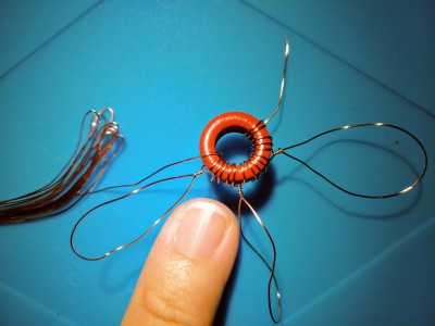
However, regarding winding the transformer, I wanted to avoid bad surprises and made sure that the transformer ends up wound the right(-handed) way to best match the holes on the PCB, although I would be using my left hand to fiddle the wire. So, how do it? First of all, the whole description in the manual is very lengthy and quite hard to follow. Luckily, the actual winding process isn’t that complicated, but forming it into words is. Please take the time to read and understand it thoroughly. Because, as a leftie, you should do the windings in the opposite order: You start at the “end”, do the three short windings (Secondary 1, Primary, Secondary 2) while turning the ring anti-clockwise, then do the long Secondary 3 winding, after which you end up at the “start”. Second important thing to consider is to always stick the wire through the ring core from behind. That way, the transformer ends up just as shown in the manual, and you can perfectly poke the wire ends through the right holes.
I noticed, the 40 m variant of the QCX is the lowest band where the needed transformer windings can be placed on the ring core without overlaps.
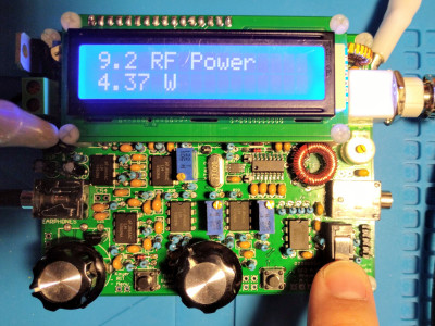
You finish the assembly with the largest components, and these pose no challenge anymore. A magic moment is the first power-up, this showed me that the digital path of the QCX was okay!
Side gig: To go through the tuning process, you need a dummy load that can bear at least the QCX’s 5 W output. I had also ordered the 20 W dummy load kit from QRP-Labs.com. Assembling it was also quite fun—and, of course, I also made a mistake there: That dummy load is constructed with 20× 1 kΩ resistors in parallel (thus 50 Ω), using a sandwiched PCB layout. Instead of applying the upper PCB upside-down, I accidentally soldered it with the printed side up. Noticing my mistake, I made sure that I applied a lot of solder onto each of the resistors such that there is a high chance of connection at the opposite side of the PCB. Finally, instead of connecting both PCBs with a simple vertical wire, I poked it through the PCBs diagonally to realize proper grounding of the upper PCB. Measuring the result with the DVM and with an antenna analyzer showed that I was successful and that I could use it to tune the QCX.
Tuning the BPF to maximum amplitude was easy. But I couldn’t tune I-Q balance and phases: The QCX was “too loud” and even started to create a loud squeal at about half the gain. Following suggestions from the mailing list, I went through the first health check by measuring voltages at pins 1 and 7 of all ICs. And indeed, IC7 showed 10.8 V at pin 1 where just about 2.5 V were to be expected! For me, as a beginner, making further measurements was quite challenging. Did I solder one of the resistors too poorly? But measuring them and their connections didn’t show anything wrong. I then went on to measuring all other pins, and—lo and behold!—there wasn’t a connection between IC7 pin 2 and R20! I looked at the soldering point at the bottom, and it didn’t look too bad, but yes, with some imagination, it might have been a case of “solder at the pin tip, but not at the PCB”. When trying to fix this, the solder didn’t really want to stick to the pin! I tried to remove the solder and try again, but same result. Since pin 2 was now in danger of becoming a mess, I simply patched an artificial path between pin 2 and R20 at the bottom of the PCB, in parallel to the given path on the PCB that seemed to be broken somehow. Now finally the R’s showed the expected values, and so did the voltages then! This also fixed those other off voltages at ICs 8 and 9. I could successfully tune I-Q and phases.
Here’s a little photo show of my progress:
So: The Beginning is nigh! I could already hear other stations, and I tried an RBN test, but I wasn’t heard and I was heard. ![]() I’m still not mature enough in CW to dare to go on the air in this mode, but time is ripe! For now, I don’t care about a housing for the QCX, since it costs just as much as the QCX itself. The QCX will be my living room TRX, in use during the two hours after the kids had gone to bed, with a simple (and secret and hardly visible wire loop) antenna on my top floor balcony—which is exactly my next project. I will also go through the section of the manual that explains the HF paths and design decisions of the QCX, which is also a very important step for me, as mentioned at the beginning.
I’m still not mature enough in CW to dare to go on the air in this mode, but time is ripe! For now, I don’t care about a housing for the QCX, since it costs just as much as the QCX itself. The QCX will be my living room TRX, in use during the two hours after the kids had gone to bed, with a simple (and secret and hardly visible wire loop) antenna on my top floor balcony—which is exactly my next project. I will also go through the section of the manual that explains the HF paths and design decisions of the QCX, which is also a very important step for me, as mentioned at the beginning.
Addendum: I tuned the 27 MHz reference frequency of the QCX by listening on a commercial TRX tuned to the QCX’s output frequency until the audible tone matched the 700 Hz sidetone of the QCX. Mine turned out to be 27,005,100 Hz.
About
Calendar
| Mon | Tue | Wed | Thu | Fri | Sat | Sun |
|---|---|---|---|---|---|---|
| ← Back | January '26 | |||||
| 1 | 2 | 3 | 4 | |||
| 5 | 6 | 7 | 8 | 9 | 10 | 11 |
| 12 | 13 | 14 | 15 | 16 | 17 | 18 |
| 19 | 20 | 21 | 22 | 23 | 24 | 25 |
| 26 | 27 | 28 | 29 | 30 | 31 | |


Stephan Paukner :: syslog on : Construction report QRP-Labs.com 50W PA
Stephan Paukner :: syslog on : Construction report QRP-Labs.com QMX