Monday, March 12. 2007
Time-frequency shifts of a 2D-Gaussian

The modulated Gaussian I showed previously was just illustratory and did not consider mathematical properties such as FT-invariance. For that, it has to be periodized, normalized and centered at the borders. The MATLAB script gaussnk.m by N. Kaiblinger from the NuHAG toolbox implements this by evaluating the Gauss function on a wider interval and then wrapping it into the desired signal length. I tried to do that for the 2D case, but here I’m not sure about the term “signal length”, it should actually be the number of pixels. I wrote a first gauss2.m which creates a 2D-Gaussian on a square with almost all desired properties. However, the normalization seems to be wrong, as it does not fulfill ,
and
as desired. I have to become familiar with the discrete definition, I don’t know how the norming factors come up; maybe they consider the dimension d as a power.
What I was trying to do was doing localized FFT2’s on a test image. I shifted an arbitrarily selected Gaussian like a spotlight aver an image and did FFT2’s of that. However, on white walls the result didn’t show the desired FT-invariance of the Gaussian. So I had to think of the aforementioned normalizing tasks. Then I was confused that shifts of a Gaussian actually result in modulations on the FT-side. But shouldn’t we want to stay the FT all the same while shifting the Gaussian over a white wall in the input image (and having an unchanged Gaussian at every spot)? Yes, but only as long as we don’t want to be able to invert the FT! Here, we’d need the modulations to get back to the corresponding shifts on the input image. So, if only the spectra are interesting, one should look at the absolute values of the FT which will make the modulation factors disappear (because they have an absolute value of 1).
Another thing I came over was this; look at the following example image: On the left half is the input, and the right half shows the absolute values of the FFT2. The input almost looks like a modulated Gaussian. Why doesn’t it simply shift on the output image? Because in the input, the black values of the surroundings match the black values of the line pattern! If the input should represent a modulated Gaussian, the black lines should have value -1, and the surroundings a gray level of 0. I’ll correct this soon.
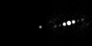
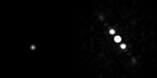
I like to rotate the output by 90° to match the orientation of the shifts with that of the lines in the input. Notice that I shifted the mid tones in the output image and that I always get another Gaussian in the center. This is the one I have to get rid of. Also, I get some kind of symmetry, the cause of which I haven’t found out yet but might also be due to the scaling issue.
For that, I visualized the TF- and FT-behavior of my 2D-Gaussian:

See how it is centered at the corners; remember that we have a periodic image consisting of this tile repeated infinitely often. For visualisation, I prefer to look at the fftshift’ed versions to have that center in the middle of the image. I compare it with its FFT2:


Just as we want it to be!
Now I do a translation of the input and look what happens at the output. I shift it upwards by 20 pixels and do the FFT2:


The translation yields a modulation on the FT side. Note that this fact is a general property, not only one of the Gaussian!
Now we do a modulation of the input and see what happens at the output. A modulation in the discrete case considers frequencies ,

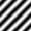
Note: This is the function for
and
.
OK, let’s look at what a modulation does to our Gaussian on the FT side:


No surprise for us and what we actually wanted to see in the aforementioned local FT’s of the test image. Sure, one could interject now that those modulated Gaussians were additionally shifted in my experiments. Let’s see what happens in that case:



The left image has a modulation and translation, and its FT—seen in the middle—has a modulation corresponding to the previous translation and a translation corresponding to the previous modulation. If one is not interested in the modulations occuring because of the wanderings of the “light spot” on the input, the look at the abolute values of the FT might be preferred, as shown in the third image. The location of the spot in the third image tells what pure frequency was contained in the light spot on the first image.
What if we commute translation and modulation on the input? Well, we just get a scaling factor which isn’t visible in the images when we keep the color depth from black to white.
That’s all for now. I won’t publish the gauss2.m before I’m sure that it’s correct. I’ll also have to implement scripts for doing 2D-modulations and 2D-translations.
About
Calendar
| Mon | Tue | Wed | Thu | Fri | Sat | Sun |
|---|---|---|---|---|---|---|
| ← Back | February '26 | |||||
| 1 | ||||||
| 2 | 3 | 4 | 5 | 6 | 7 | 8 |
| 9 | 10 | 11 | 12 | 13 | 14 | 15 |
| 16 | 17 | 18 | 19 | 20 | 21 | 22 |
| 23 | 24 | 25 | 26 | 27 | 28 | |
Logbook of Stephan Paukner on : Modulating a 2D-Gaussian
Logbook of Stephan Paukner on : Time-frequency shifts of a 2D-Gaussian (Addendum)